A smart device designed to connect hikers in the wilderness.
Walkie Walkie combines the sturdiness of a hiking stick with the communication features,
ensuring you can keep in contact with your hiking party despite physical separation.
This project was a part of the Fall 2025 Product Design showcase at Duke.
Overview
Our team set out to solve two problems with hiking: communication and convenience.
Hiking as a group can become complicated.
Oftentimes, groups will have to walk in a single-file line as paths become narrow,
or groups will split as they hike at different paces,
creating a communication barrier between ends of the group.
Our solution achieves communication over standard FRS radio frequencies,
ensuring reliable transmission at distance and in obstructed environments.
Additionally, hikers want to carry as little as
possible while on the trail, as additional weight
makes it harder to trek long distances.
At the same time, it is annoying to rummage through a backpack
to find different items, yet hiking sticks are already in hikers' hands.
We improve convenience by providing new features at hikers' fingertips.
Skills
PCB Design and Fabrication - KiCad
Electrical Schematics
Microcontroller Programming - Arduino IDE (C/C++)
3D Printing
Casting and Molding
Mechanical
Mechanical system overview
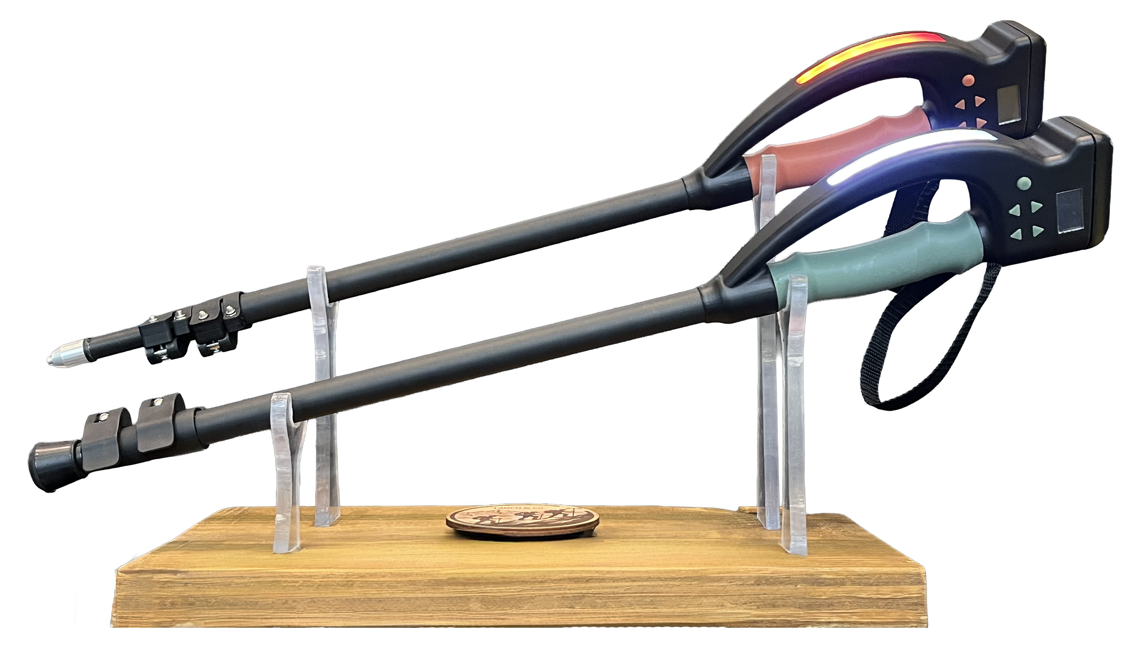
The team custom designed and iterated through many versions of the handle using Solidworks,
ultimately landing on a pommel-style top to accommodate more ways to hold
the stick. The main body of the handle was resin printed with grey resin
mainly due to its complicated geometry. Resin was also chosen over PLA or
other plastics for a smoother finish and higher strength.
The handle was then coated with black paint and a protective clear coating.
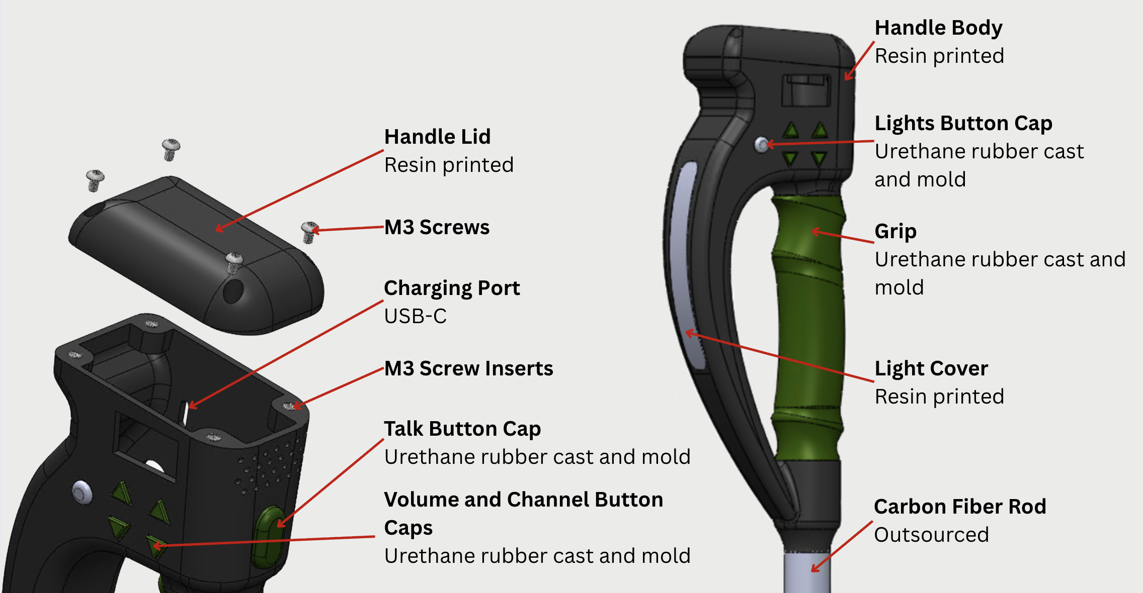
The body and lid of the handle are held together with 4 M3 screws that screw
into inserts that are installed into the body of the handle.
The cover for the flashlight was also resin printed to conform to the
curved shape of the handle. This component was printed clear and polished
for a smoother finish. To prevent individual LEDs from being seen, a light
diffusing sheet was attached to the back of the light cover.
The rubber grip and button covers were also custom designed and molded by
the team, which is discussed further below. Each component was carefully
designed and tolerances to fit.
The carbon tubes of the stick were outsourced and cut to size. The team
decided to make an adjustable hiking pole so it could be personalized to
each user's desired length. The tubes
are 2mm thick with varying diameters for the telescoping features. The
latches, which prevent the tubes from falling out of each other, were also outsourced.
The team invested in high quality and secure latches to prevent any slippage
which is a safety hazard while hiking over dangerous terrain. The largest diameter
carbon tube extends through the rubber grip, holding it in place, until it hits an extruded
stopper at the buttom of the top part of the handle near the talk-to-speak button. This reinforces
the structure of the stick and distributes the load path through the carbon tubes instead
of the resin handle. This prevents the handle from experiencing excessive load when the user
exerts their weight onto the stick.
Rubber parts and their 3D-printed molds
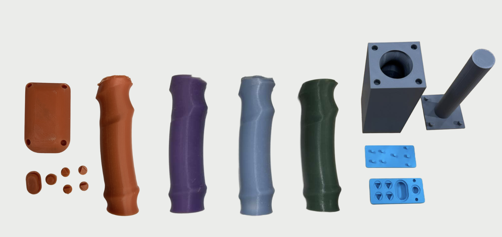
The grips and buttons were all molded using Smooth-On VytaFlex 60 (Liquid Urethane Rubber).
The team experimented with multiple rubbers, but ultimately ended up choosing urethane rubber
because of its hardness and durability. Different colors were achieved by mixing dye into the
rubber before pouring.
The molds were made by extruding negatives in CAD over the grip and buttons to create
the desired shape. The grip mold had 4 alignment holes to make sure the center of the
grip was in the right place. The button mold also had alignment holes to make sure their
centers were also in the correct place. This was critical to making sure that the buttons
fit in the right place during installation with the electronic physical buttons, and
ensuring the grip aligned with the handle as well.
Tip design
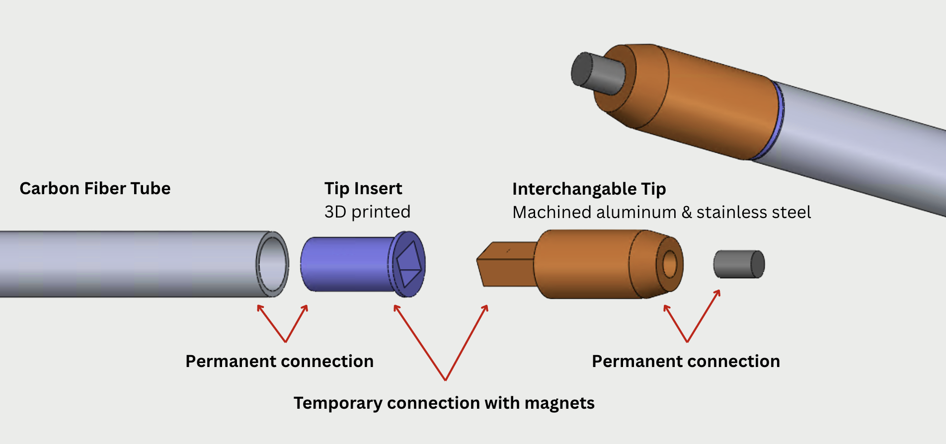
The other end of the hiking stick houses the tips. Walkie Walkie has multiple
interchangeable tips to accommodate different terrain: dirt, gravel, pavement,
and snow. The tip insert is permanently attached to the carbon fiber tubes with
a magnet inside. The interchangeable tips also have a magnet that is attracted
to the end of the pole.
Users can easily switch which tip they need by pulling it straight out of the pole.
The mating shape between the female and male parts of the tip were chosen to be a
rectangle to prevent any rotation. The main tip attachment for dirt and gravel was
machined out of aluminum with a stainless steel rod at the top for strength.
Electrical
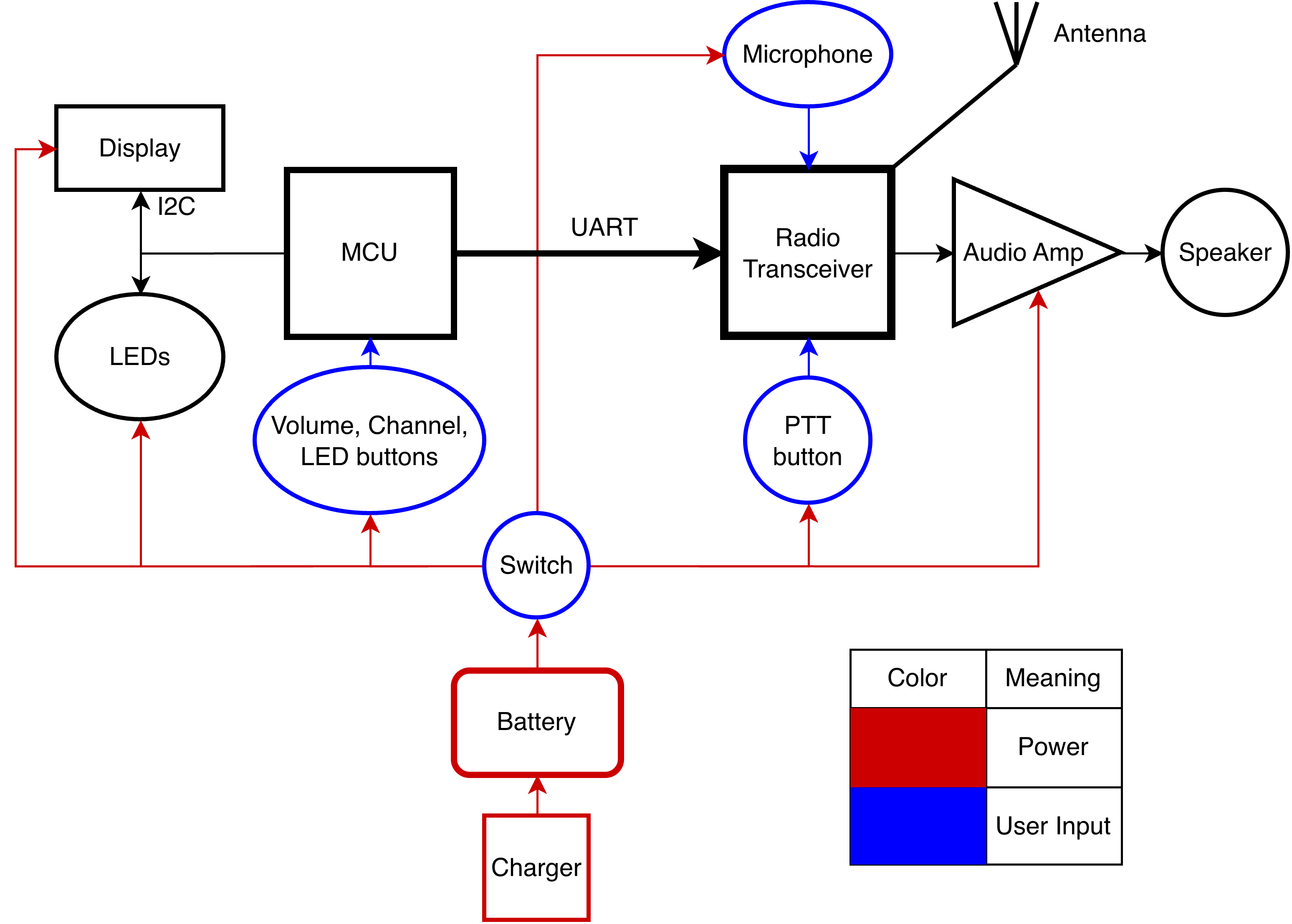
Electrical system architecture overview
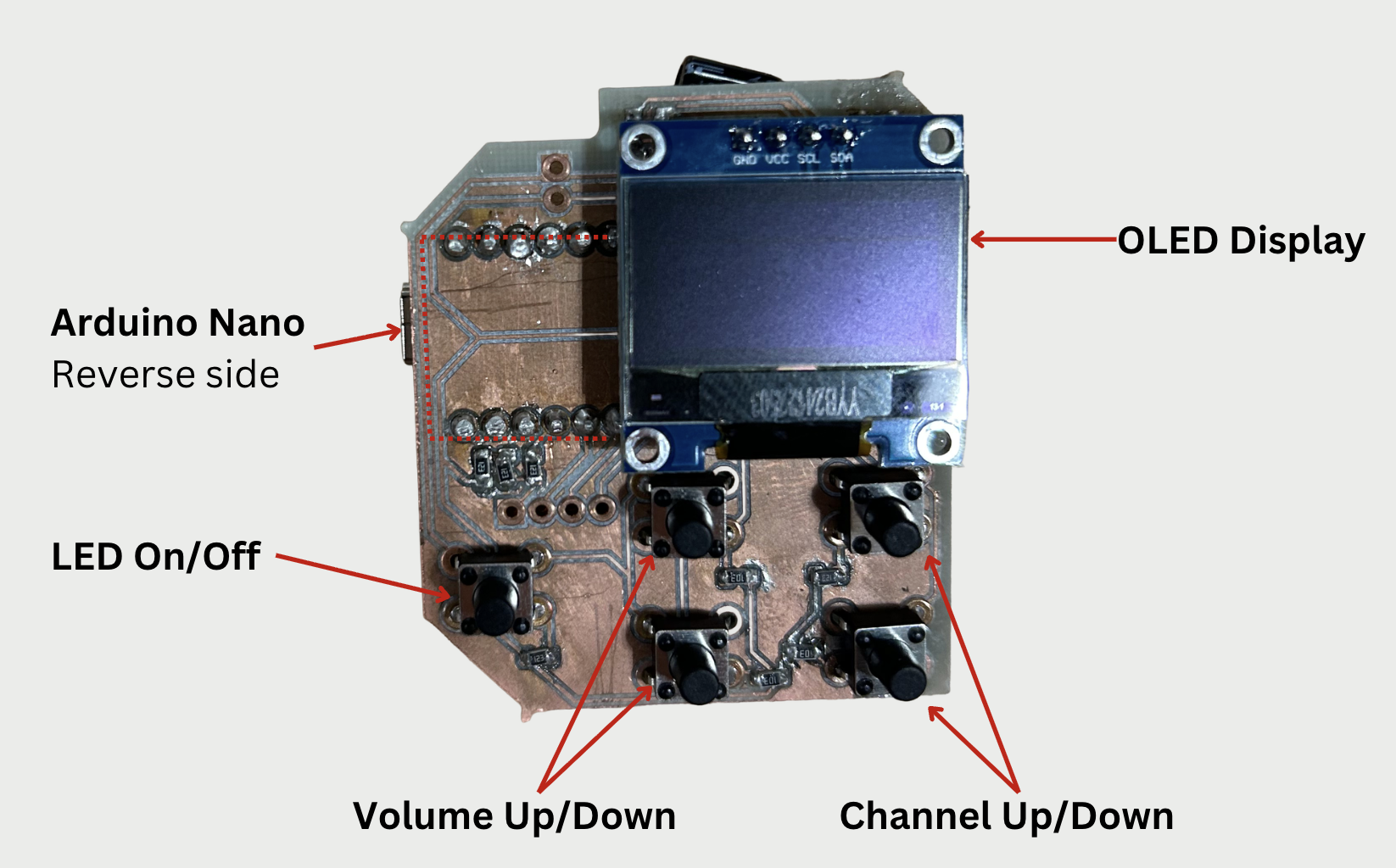
Walkie Walkie uses an Arduino Nano to control an OLED display,
program RGB LEDs on the front of the device, and handle user
input via pushbuttons. The buttons allow the user to activate
the front LEDs, change speaker volume, and select radio channel.
The volume level and channel number are shown on the display for
five seconds after device power-on and any button press, turning
off to save power after this timeout.
The microcontroller also sends commands to a radio transceiver
(NiceRF SA818s UHF) over UART. These commands include changing
speaker volume, channel frequency, and in future versions the
squelch level and transmission power level.
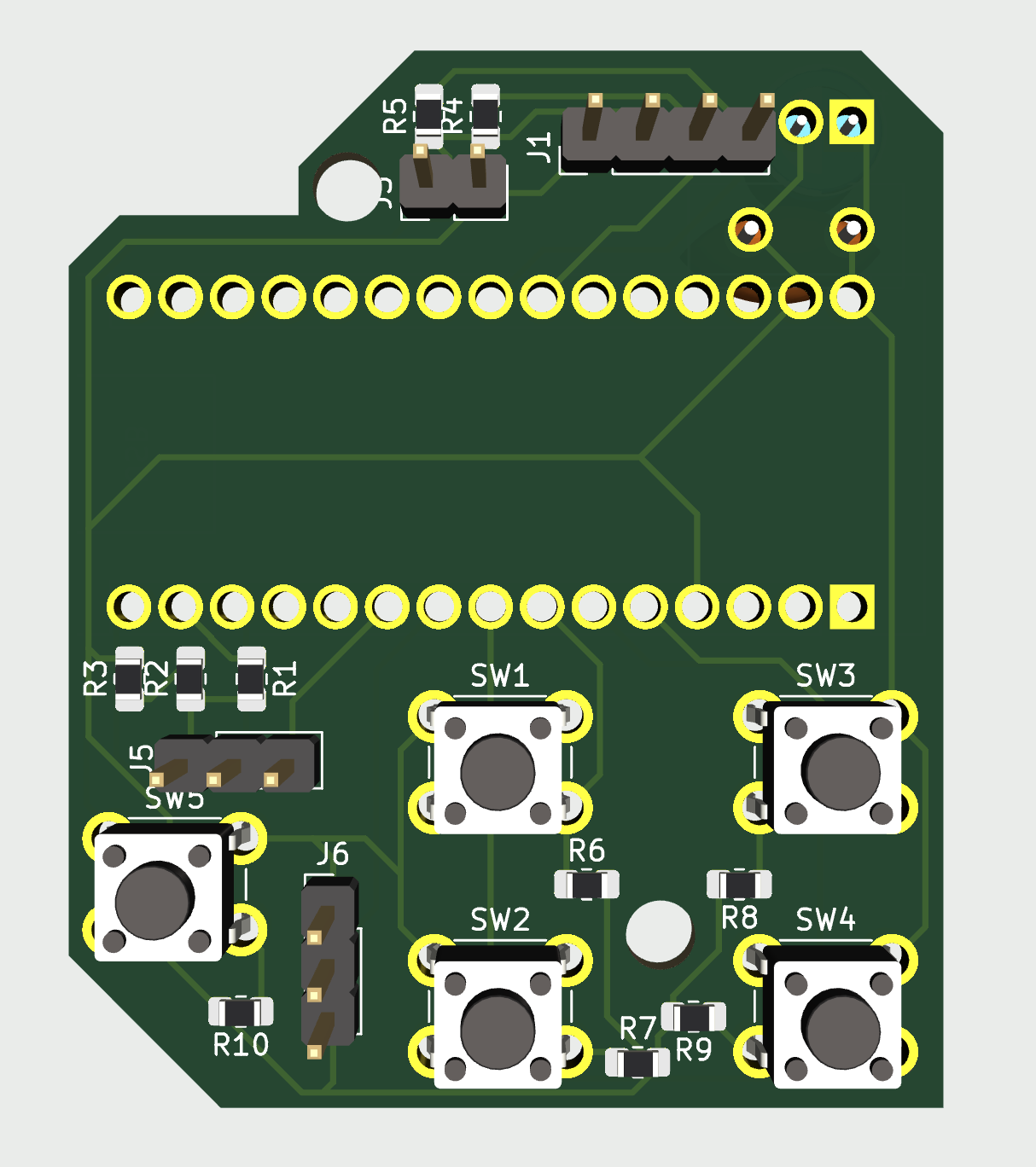
We designed two PCBs that fit within the device. The display /
microcontroller PCB holds the OLED display and buttons on one side,
with the Arduino mounted on the reverse.
There are two connectors from this PCB, one to the front LEDs and
the other to the second PCB.
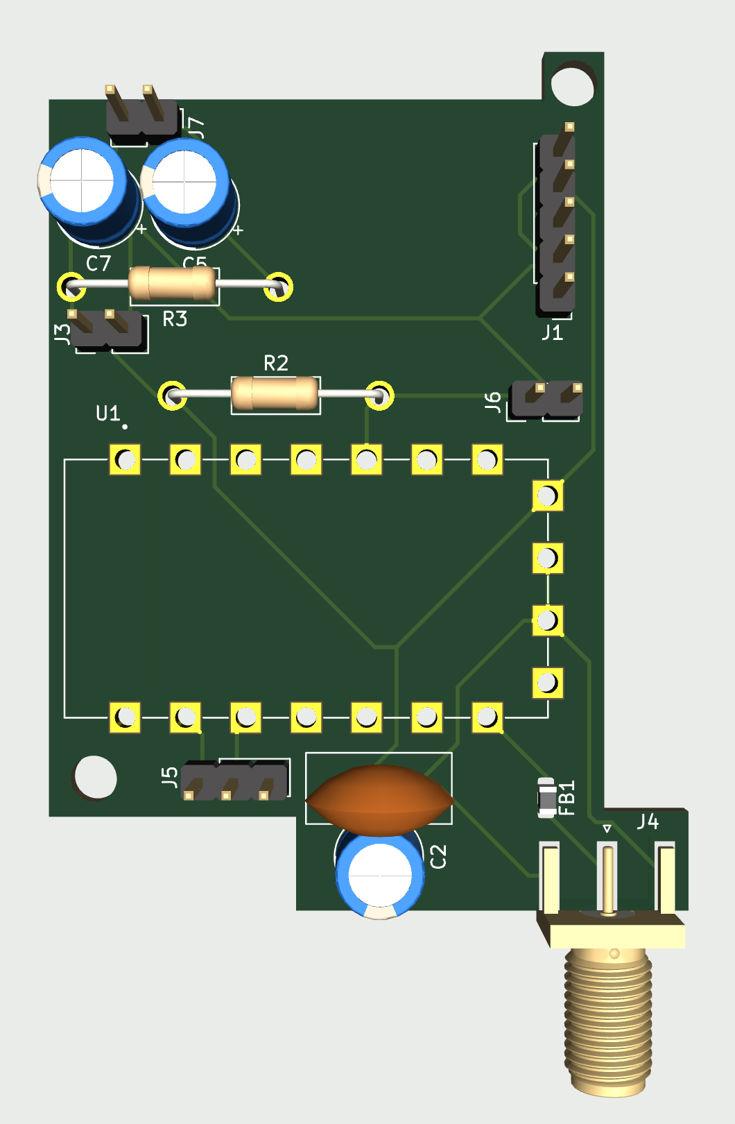
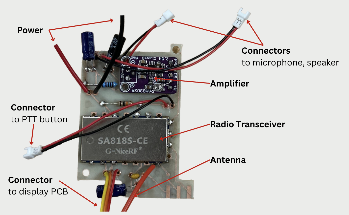
The radio PCB has the radio transceiver, amplifier, and connectors
for the microphone, speaker, and PTT button.
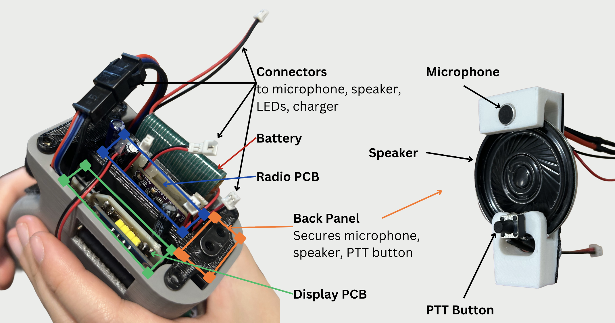
Both PCBs have screw holes that allow them to connect to our
3D-printed electronics bay. The bay has a back panel
that secures the microphone, speaker, and PTT button despite
these components not being on a PCB.
The electrical system is powered by a rechargeable 3.7 V LiPo battery.
The device uses USB-C, accessible from a port next to the power switch.
Completed PCBs
Electronics Bay and Back Panel
Software
The software for the device is straightforward, written in a single
Arduino script.
First, all of the components are initialized with
the display using I2C, the LEDs using Adafruit’s NeoPixel library,
and communication to the radio module established with serial over
two digital pins.
After initialization, polling is used to check button states and perform
necessary actions in response to any presses, including sending commands
to the radio transceiver or switching LEDs on or off. See the linked
GitHub repo for complete code.
One challenge was getting the components running properly, specifically
within the Arduino’s timing constraints, which were further limited
running on the LiPo battery. We originally used the SoftwareSerial
library for UART over two digital pins. This worked well on its own,
but after putting everything together the microcontroller couldn’t keep
everything running.
It turns out the SoftwareSerial library uses expensive polling,
but another library, NewSoftSerial, implements the same functionality
with interrupts. There were several issues getting the NewSoftSerial
library running on current Arduino IDE versions, so we made a few fixes
to the library for anyone to use:
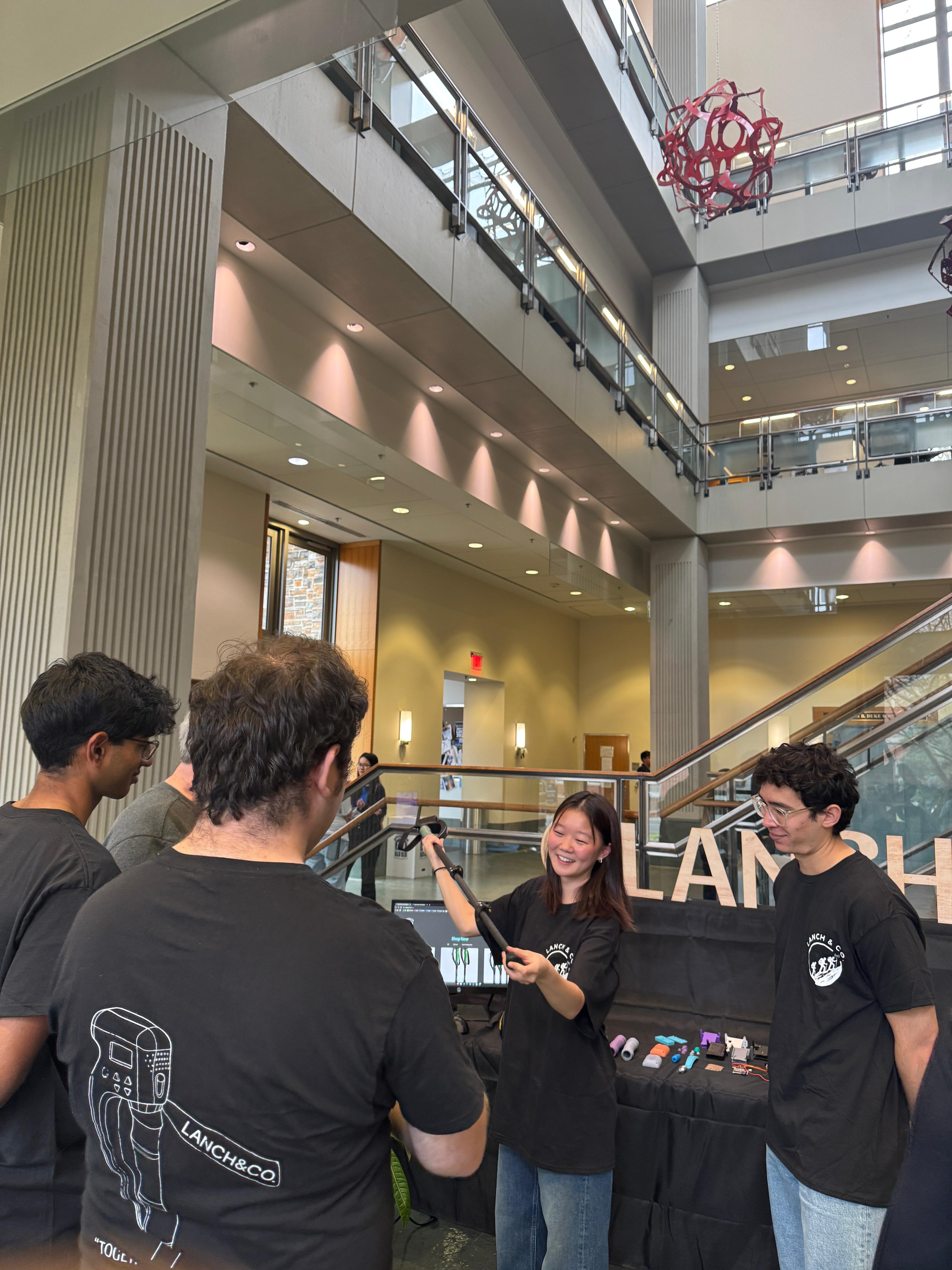
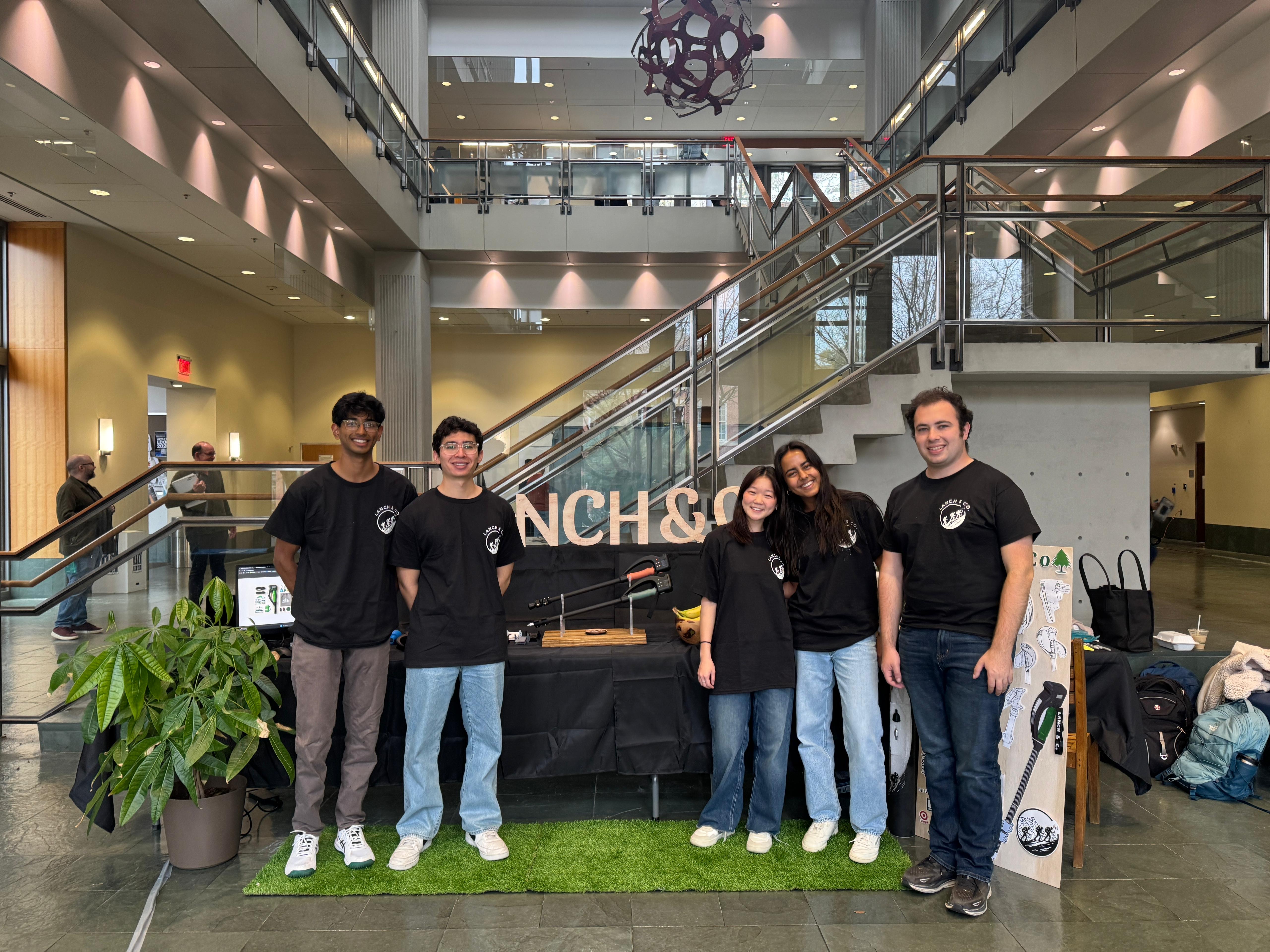
We had the opportunity to present our fully-functioning product alongside
our MEM teammates. Throughout the semester, the MEM graduate students
worked on branding, market fit, and the company and product website.
At the showcase, we demonstrated the capabilities of our product to professors,
students, and other members of the Duke community.
Team
Undergraduate:
April Lee,
Charlie Linder,
Harrison York,
Neyla Kirby,
Nikhil Arayath